Description
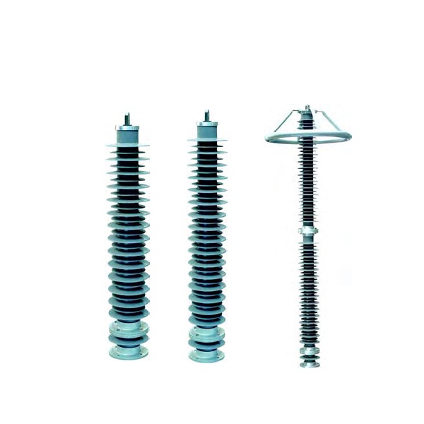
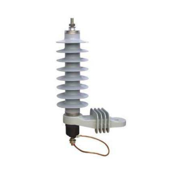
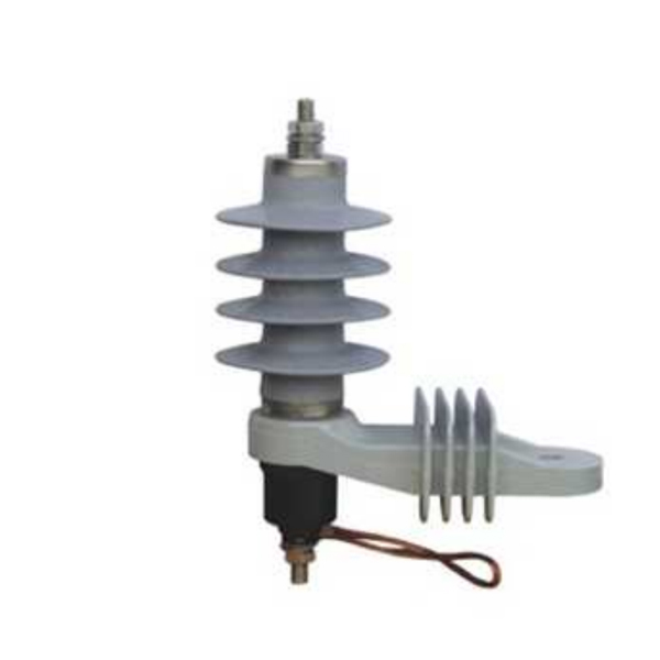
Power Substation Type Polymer Lightning Arrester
General Introduction
Wolun Polymer Lightning Arresters are manufactured to offer optimum protection to distribution equipment such as transformers and similar assets against the damaging lightning effects and similar operational conditions. These arresters perform their task with high-end improvement and fidelity towards surge switching and medium voltage networks. Maintenance of service safety for both underground and overheard setups is offered without any trouble on exposure in the outdoors for long durations. Going through precision tests have made Wolun arresters more durable & reliable.
Working Conditons
1. The ambient air temperature is no higher than +40°C, no lower than -40 °C .
2. The altitude above sea level does not exceed 1000m. ( the plateau area should be indicated when order.)
3. AC system frequency is 50Hz or 60Hz.
4. Power frequency voltage brought to bear on arrester for a long time does not exceed the continuous operation voltage of the arrester.
5. Maximum wind speed does not exceed 35m/s.
6. Te earthquake intensity does not exceed 7 degrees.
7. The pollution area should be indicated.
Features
- It adopts double sealing structure, the core encapsulates by molded silicone rubber which completely solves the sealing problem of porcelain housed products.
- It has a two-way pressure release structure.
- Its core component ZnO varistor has good pressure ratio, consistency, large flow capacity and high reliability.
- E creepage distance of porcelain housed products is wide which is suitable for IV level heavy pollution areas.
Technical Specification
| Type | Nominal System Voltage | Rated Voltage | Continuous Operating Voltage | MRV under 1/5 μ s Steeo Discharge Current | MRV under 8/20 μ s Lightning Discharge Current | MRV under 30/60 μ s Operating Discharge Current | Minmum Reference Voltage under 1 mA DC | 4/10 μ s High Current Impulse Twice (KA) | 2mS SW through-flow capacity A/18 | Line Discharge Class | |||
| 10KA | 20KA | 5KA | 10KA | 0.5KA | 1KA | ||||||||
| Y10W5-102/266 | 123 | 102 | 81 | 277 | 235 | 258 | 203 | 210 | 148 | 100 | 850 | 3 | |
| Y10W5-108/281 | 145 | 108 | 86 | 295 | 249 | 274 | 215 | 222 | 157 | 100 | 850 | 3 | |
| Y10W5-111/290 | 145 | 111 | 88 | 303 | 257 | 282 | 222 | 229 | 161 | 100 | 850 | 3 | |
| Y10W5-120/313 | 145 | 120 | 98 | 327 | 277 | 304 | 239 | 247 | 174 | 100 | 850 | 3 | |
| Y10W5-126/329 | 145 | 126 | 100 | 344 | 291 | 320 | 251 | 259 | 183 | 100 | 850 | 3 | |
| Y10W5-132/344 | 145 | 132 | 106 | 359 | 305 | 334 | 263 | 272 | 192 | 100 | 850 | 3 | |
| Type | Nominal System Voltage | Rated Voltage | Continuous Operating Voltage | MRV under 1/5 μ s Steeo Discharge Current | MRV under 8/20 μ s Lightning Discharge Current | MRV under 30/60 μ s Operating Discharge Current | Minmum Reference Voltage under 1 mA DC | 4/10 μ s High Current Impulse Twice (KA) | 2mS SW through-flow capacity A/18 | Line Discharge Class | |||
| 5KA | 10KA | 5KA | 10KA | 0.25KA | 0.5KA | ||||||||
| Y10W5-192/500 | 220 | 192 | 150 | 560 | 500 | 426 | 280 | 100 | 800 | 3 | |||
| Y10W5-200/520 | 220 | 200 | 156 | 582 | 520 | 442 | 290 | 100 | 800 | 3 | |||
| Y10W5-204/532 | 220 | 204 | 159 | 594 | 532 | 452 | 296 | 100 | 800 | 3 | |||
| Y10W5-216/562 | 220 | 216 | 168.5 | 630 | 562 | 478 | 314 | 100 | 800 | 3 | |||
|
||||||||||||||||||||||||||||||||||||||||||||||||||||||||||||||||||||||||||||||||||||||||||||||||||||||||


